mBlock Extension:
MAXI Starter Kit (ver. 1.1.0)
Extension for Arduino and teaching MAXI Starter Kit. This extension contains functions and procedures to support all modules of the MAXI Starter Kit. The MAXI Starter Kit contains about thirty lessons for Arduino. There are many additional devices such as LCD, servo, temperature, humidity sensor, IR receiver, RFID reader and more in this kit. With this our extension, you can easily create all the lessons from the tutorial for this Arduino-kit in mBlock.
The whole extension is divided into thirteen thematic parts:
 |
Pins Config |
- Setting the digital pin to the PULLUP mode and its subsequent reading.

- Setting the A (Analog) pin to the PULLUP mode and its subsequent reading.

- Setting the A (analog) pin to digital mode and setting the HIGH/LOW level.

- digital level LOW

- digital level HIGH

 |
I2C Scanner |
- A list of all I2C devices connected to Arduino will be listed to the serial monitor.

 |
LCD I2C Display |
- Setting the LDC display dimensions (column/rows) of the specified I2C address.

- Switching on/off the backlight of the LCD display of the specified I2C address.

- Deleting the contents of the LCD display of the specified I2C address.

- Setting the cursor to the specified column, row position on the LCD display of the specified I2C address.

- Display the entered text at the current cursor position on the LCD of the entered I2C address.

- Setting the direction of the displayed text (right to left or left to right) of the LCD display of the specified I2C address.

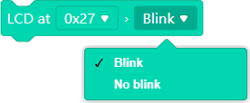
- Setting the flashing of the LCD display of the specified I2C address.
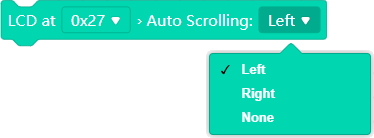
- Setting the text scrolling option (left, right, none) on the LCD display of the specified I2C address.
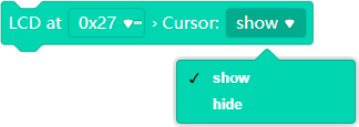
- Setting the cursor display (show/hide) on the LCD display of the specified I2C address.
 |
Strings variables |
- Setting the content of the string variable (variables are numbered for differentiation).

- Getting the content of the specified (specified by number) string variable.

- Getting the length of the specified (specified by number) string variable content.

- Replacing the expression "text1" with the expression "text2" in the specified string variable.

- Get a substring from the specified string. The substring is determined by the sequence number of the first character and its total length.

- Getting the position (character order number) of the search expression "TEXT" in the specified (specified by number) string variable. The start of the search can be selected by the character sequence number of the content of the text variable. The result is always the sequence number from the absolute start of the content of the specified text variable!

- Conversion of a real number to a text variable with a choice of displayed decimal places.

 |
Arrays |
- Declaration of an array of numeric/string variables. The number of variables must be specified. The number of variables of the array is specified, not the highest index of the array! The first item of the array has index 0 (an array with indexes 0 and 1 already has two elements!)

- Sets the selected numeric value to the specified array variable.

- Set the selected string value to the specified array variable.

- Get the contents of the specified item of the selected array.

 |
Shift Register |
- Setting the control pins (Latch, Data, Clock) of the shift register.

- Select the direction of sending the byte to the shift register (Most Significant Bit first / Least Significant Bit first).

 |
Time/Date |
- Setting the control pins of the RTC module DC1302.

- Setting time/date to RTC module DS1302. The data format is: HH:MM:SS / DD-MM-20YY.

- Setting time/date to Arduino module. The data format is: HH:MM:SS / DD-MM-20YY

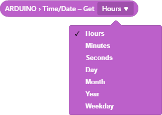
- Getting one of the selected data (hour, minute, …, day, month, year). The data is read from the Arduino module.
- Synchronization of time data from RTC module DS1302 to Arduino module. It can be used, for example, after starting the Arduino module to retrieve the current values from the RTC module, which is backed up by a battery.

 |
DHT Sensor |
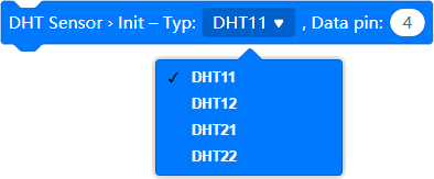
- Setting the DHT sensor type and selecting its data pin.
- Reading the current temperature value from the measuring module.

- Reading the current relative humidity value from the measuring module.

 |
Stepper Motor |
- Initializing a 4-wire stepper motor – setting the motor identification number, number of steps per revolution and setting the control pins.

- Initializing a 2-wire stepper motor – setting the motor identification number, number of steps per revolution and setting the control pins.

- Initializing a 5-wire stepper motor – setting the motor identification number, number of steps per revolution and setting the control pins.

- Setting the rotation speed (rpm) of the specified stepper motor.

- Enter the number of steps for the specified stepper motor. Entering a negative number of steps will change the direction of rotation of the motor.

 |
Servo |
- Servo initialization – selecting a specific number for the servo, setting the control pin.

- Setting the rotation angle for the servo specified by number.

- Reading the current servo rotation position. The servo is again determined by a specific number.

 |
IR Remote |
- Infra Red receiver initialization – setting the data pin.

- A program block that executes the moment some data has been received by the IR receiver.

- Reading the data received by the IR receiver.

 |
RFID Reader |
- RFID module initialization – setting of control pins (IRQ, SCK, MOSI, MISO, SDA, RTS)

- A program block that starts when the RFID module reads an RFID element.

- Reading the identification number of the read RFID element.

 |
KeyPad |
- 4×4 keypad control pin settings (columns × rows)

- 3×4 keypad control pin settings (columns × rows)

- 3×3 keypad control pin settings (columns × rows)

- Redefining the keyboard character at the column/row position.

- Start using the set and defined keyboard.

- Scan keyboard status. After this command, it is possible to see if a key has been pressed and which key has been pressed.

- A logical expression that tells if any key has been pressed.

- Getting the symbol of the key on the keyboard that was pressed.

Examples:
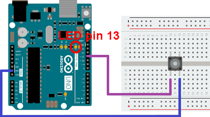
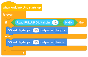
Example 1: (Pins Config) – Switching on the internal LED (connected to pin 13) using an external button.
Example 2: (LCD I2C Display) – Display any text on the LCD display with I2C controller.
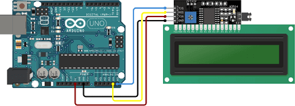
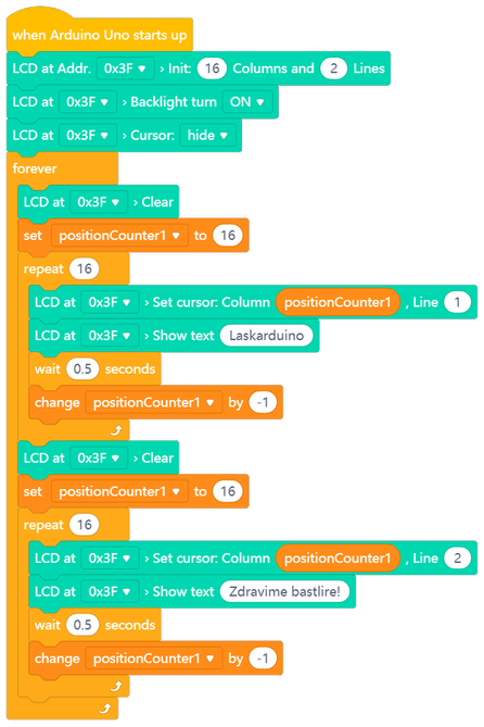
Example 3: (Shift Register + Arrays) – LED segment control using shift register + use of arrays variable
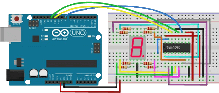
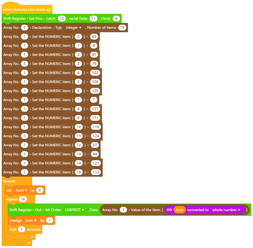
Example 4: (RTC DC1302 + LCD Display + Arrays) – Using the RTC module with LCD diplay (I2C controller) and array-type variables
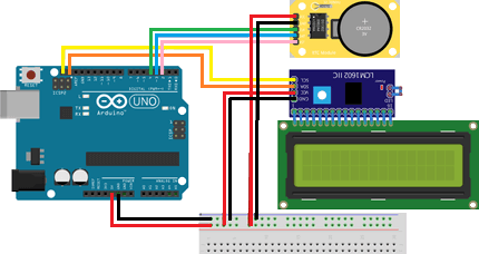
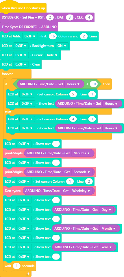
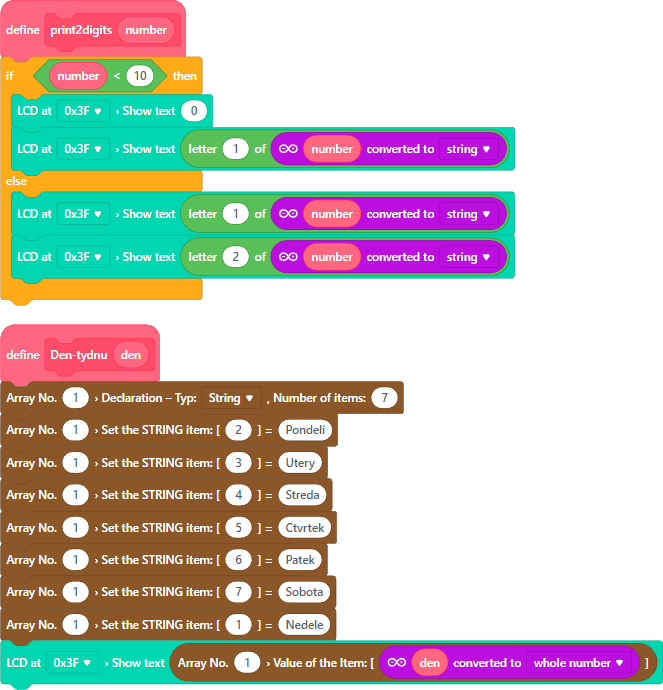
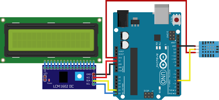
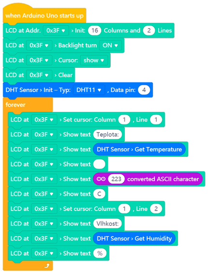
Example 5: (DHT11 + LCD Display) – Using the DHT11 sensor and LCD display (I2C controller) as a temperature and relative humidity sensor.
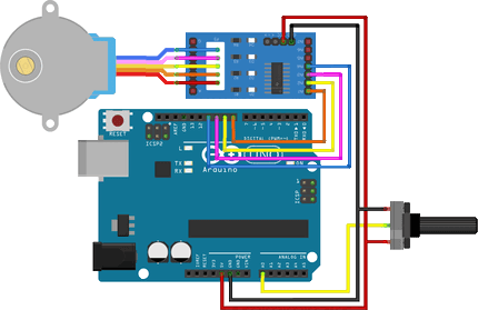
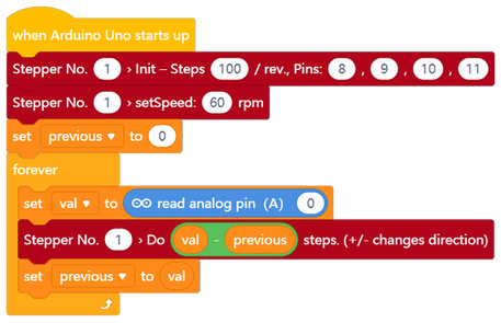
Example 6: (Stepper Motor) – Rotate the stepper motor using a potentiometer connected to the analog input.
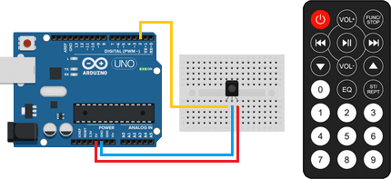
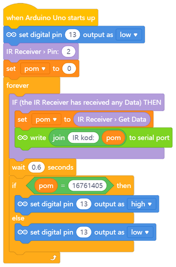
Example 6: (IR Remote) – Simple IR remote control reacting only to the PLAY button.
More examples of using will be gradually added… (Maybe… 😉)