mBlock Extension:
pinAout (ver. 0.0.3)
Pins A0-A5 are usually designated as analog inputs on the Arduino module. Also in the mBlock application, pins A0-A5 cannot be set as digital output by default. The purpose of this extension pinAout is to set pins A0-A5 as a digital output and to set the output digital value (HIGH/LOW). This extension is designed for application mBlock (version 5).
- It is possible to select one of the pins
A0-A5and write the output digital valuelow/highon it. The pin is automatically configured as a digital output and this value is written. (The pin can no longer be used as an analog input in this program!) 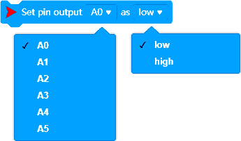
Example:
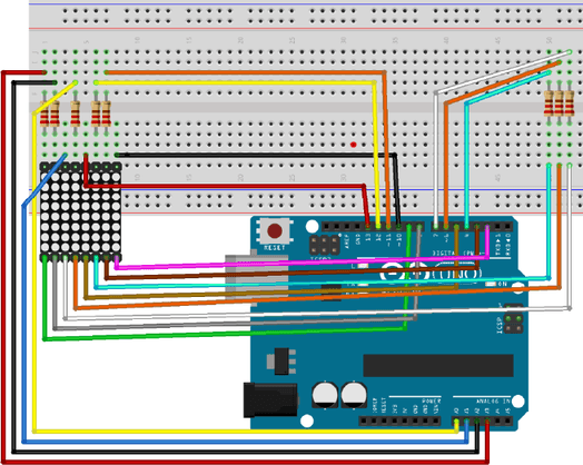
Look at the following image. This is the connection diagram of the 8×8 LED matrix to the Arduino module. To control the matrix, we need many output pins – also pins A0-A3.
 |
Arduino UNO pin | LED Matrix pin |
|---|---|---|
| A0 | 13 | |
| A1 | 14 | |
| A2 | 15 | |
| A3 | 16 | |
| 2 | 8 | |
| 3 | 7 | |
| 4 | 6 | |
| 5 | 5 | |
| 6 | 4 | |
| 7 | 3 | |
| 8 | 2 | |
| 9 | 1 | |
| 10 | 9 | |
| 11 | 10 | |
| 12 | 11 | |
| 13 | 12 |
When you use the pinAout extension, you can set outputs A0-A3 to outputs and control the LED matrix with mBlock! App mBlock is a good environment for Arduino module programming.
What about to use the LED matrix and mBlock to display a Valentine's heart?
| 128 | 64 | 32 | 16 | 8 | 4 | 2 | 1 | |
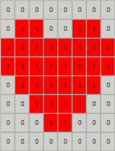 |
0 | |||||||
| 102 | ||||||||
| 255 | ||||||||
| 255 | ||||||||
| 126 | ||||||||
| 60 | ||||||||
| 24 | ||||||||
| 0 | ||||||||
There is nothing easier with the pinAout extension! 🙂
The pinAout extension blocks are marked with a red double arrow in the following program listing. In the picture you can see the main program and its subroutine SetColumns. The Set pin Output [A0-A5] as [high/low] command is used in both parts of the code.
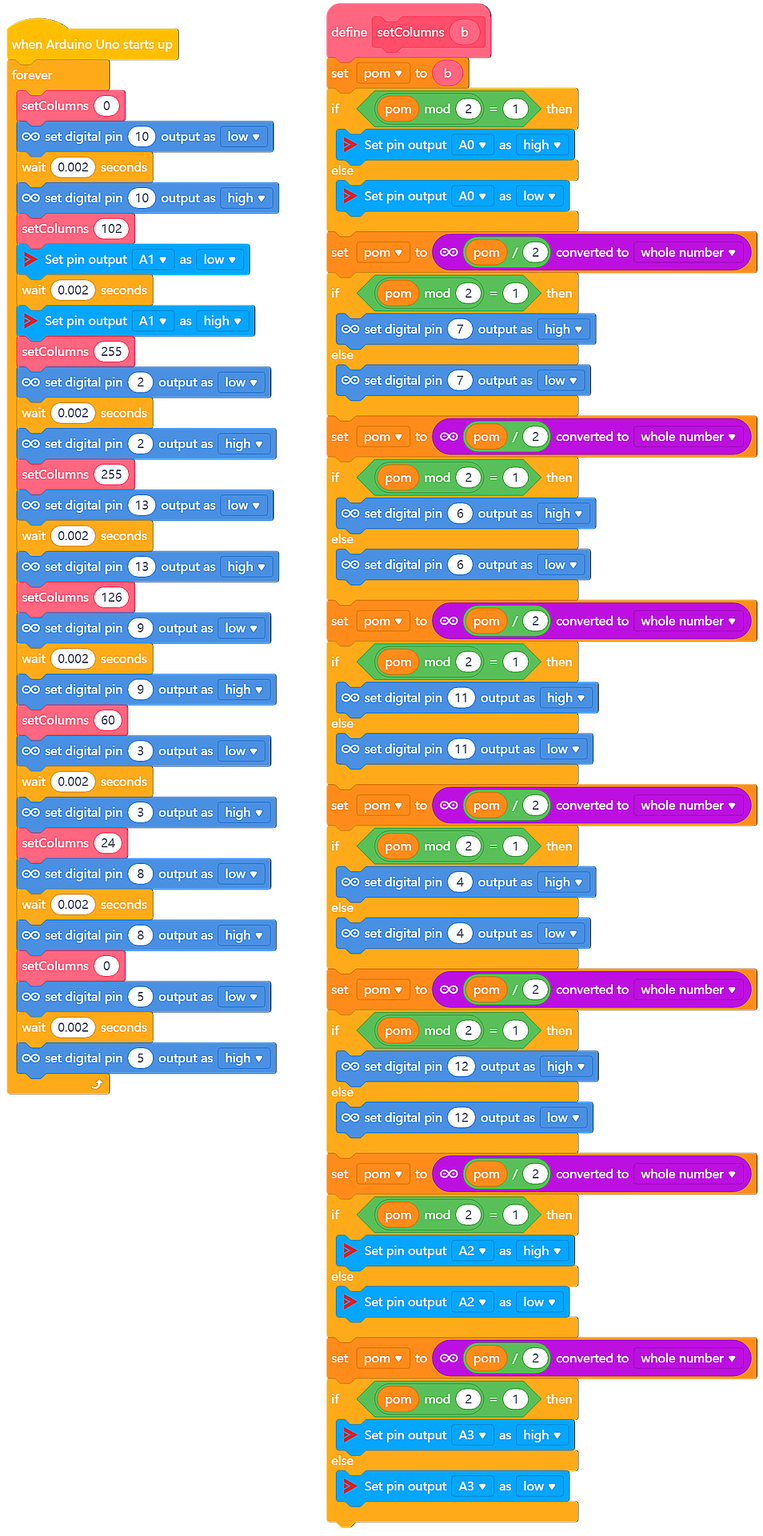
And this is the real result!
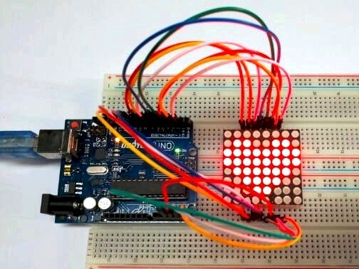
Pins A0-A3 are used as digital outputs for controlling the 8×8 LED matrix.
And all thanks to the pinAout mBlock 5 Extension!